
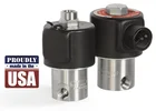
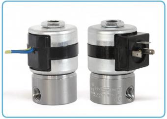
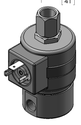
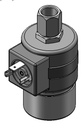
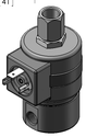
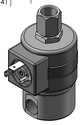
3-Way Normally Closed Valve (Piped Exhaust)
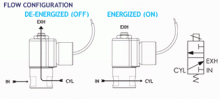
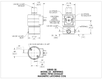
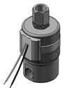
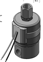
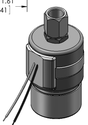
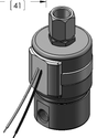
3-Way Reverse Polarity Magnet Latching Valve — Piped Exhaust This type of valve is often used in remote areas where continuous power may not be available or with battery-powered portable equipment where power capacity is limited, as it only uses power during latching and un-latching It is also valuable in equipment where coil heating, due to continuous application of power, is undesirable. Air and other fluids are compatible with standard Buna seals. Hot water, steam, gasoline, oils, some hydraulic fluids, and many other media require special seal materials.
Neutral (−) a. Pulse Yellow lead to Positive (+) to latch b. Pulse Blue lead to Positive (+) to un-latch
Positive (+) a. Pulse Yellow lead to Neutral (−) to un-latch b. Pulse Blue lead to Neutral (−) to latch
| MAX. OPER. | VALVE NUMBER DIN COIL | VALVE NUMBER | ||||||
|---|---|---|---|---|---|---|---|---|
| PRESS. DIFF. | ORIFICE SIZE | CV FACTOR | (2 TERMINALS WITH GROUND) | 2 WIRE COIL | ||||
| DC | INLET | EXH. | INLET. | EXH. | 1/8 NPT PORTS | 1/4 NPT PORTS | 1/8 NPT PORTS | 1/4 NPT PORTS |
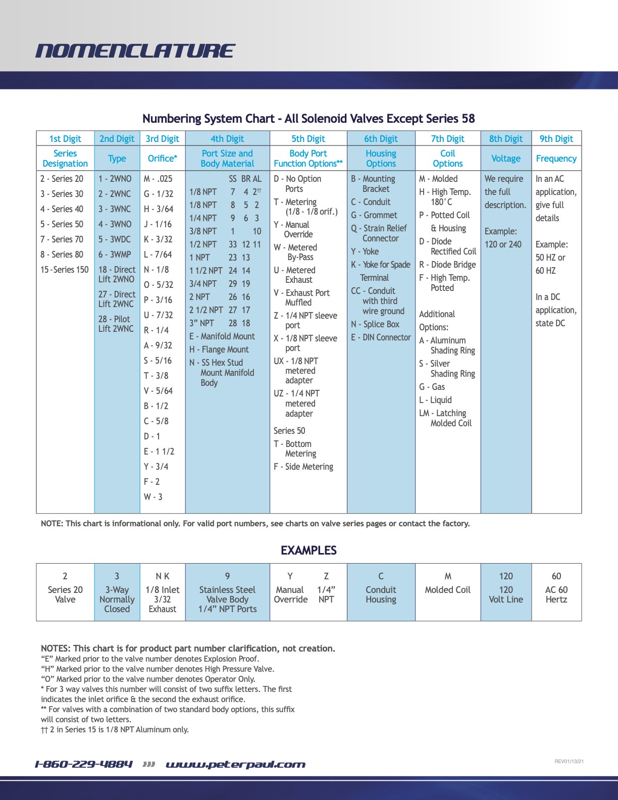
| 400 | 1/32 | 1/32 | .024 | .024 | 23GG7XELM-∆ | 23GG9ZELM-∆ | 23GG7XGLM-∆ | 23GG9ZGLM-∆ |
| 150 | 3/64 | 1/16 | .052 | .095 | 23HJ7XELM-∆ | 23HJ9ZELM-∆ | 23HJ7XGLM-∆ | 23HJ9ZGLM-∆ |
| 100 | 1/16 | 1/16 | .095 | .095 | 23JJ7XELM-∆ | 23JJ9ZELM-∆ | 23JJ7XGLM-∆ | 23JJ9ZGLM-∆ |
| 100 | 1/16 | 3/32 | .095 | .156 | 23JK7XELM-∆ | 23JK9ZELM-∆ | 23JK7XGLM-∆ | 23JK9ZGLM-∆ |
| 75 | 3/32 | 3/32 | .156 | .156 | 23KK7XELM-∆ | 23KK9ZELM-∆ | 23KK7XGLM-∆ | 23KK9ZGLM-∆ |
| 50 | 1/8 | 3/32 | .214 | .156 | 23NK7XELM-∆ | 23NK9ZELM-∆ | 23NK7XGLM-∆ | 23NK9ZGLM-∆ |
| 20 | 3/16 | 3/32 | .500 | .156 | 23PK7XELM-∆ | 23PK9ZELM-∆ | 23PK7XGLM-∆ | 23PK9ZGLM-∆ |
Ordering Information:
When ordering valves or repair packs add voltage and frequency to complete valve number. for examples: valve (23JJ7XELM 12/DC) repair pack (K23JJXJ DC)
When ordering operators add the letter “O” to the front of the valve number, replace body port number with the letter “D”: example: operator (O23JJDXELM 12/DC)
Seal Material: Replace ∆ with desired code -Blank = Nitrile (Buna) S = Low Temp Buna. N = FKM* E = Neoprene A = EPDM
Operating Conditions
- Media
- Air and other fluids compatible with standard Buna seals. Hot water, steam, gasoline, oils, some hydraulic fluids, and many other media require special seal materials. (Series 20 pressure ratings may change due to the viscosity of the liquid.)*
- Valve Temperature Range
- Standard Valves – 0°F (-18°C) to 104°F (40°C) ambient; 0°F (-18°C) to 150°F (65°C) media. Optional Valves – can tolerate much higher or much lower ambient and media temperatures.*
- Maximum Operating Pressure Differentials
- See table above.
- Burst Pressure
- 5000 PSI
- Leakage
- Bubble tight for standard valves.
- Vacuum
- To 5 Microns*
Electrical Characteristics
- Coil Voltage
- 12, 24/DC
- Nominal Power
- DC — 10.0 Watts
- Coil Construction
- Molded Class B with DIN 43650 Form A Connector (Std.), Leadwires (Opt.) For your convenience we have the female DIN style mating connector No. 20-198** available for an additional fee.*
- Typical Response Time on Air
- Approximate 50 millisecond pulse to energize and de-energize.
- Operating Speed
- Up to 600 CPM
Mechanical Characteristics
- Body
- Stainless Steel (Std.) or Brass (Opt.)
- Internal Components
- Stainless Steel
- Elastomers
- Nitrile (Buna) (Std.). Many other elastomers available.*
- Orifice Diameter
- See table above.
- Porting
- Standard 1/8” and 1/4” NPT (other ports available).*
- Life Expectancy
- Millions of cycles, depending on application, lubrication, etc.
- Valve Weight
- 1.2 lb average
- Repair Packs
- See table above.
- Options
- Alternate Port Locations, Metering and Alternate Elastomers* * Consult representative or factory for options and specifications.
Series 20 Model 23 Magnetic Latching
Cv Flow Formulae
PeterPaul has created this page for you so you can calculate the flow or Cv (flow coefficient) to make the relationship visible between the pressure drop (the difference in pressure between two points of a liquid/gas carrying network) and the flow rate.
The use of this flow coefficient (Cv) calculator offers a standard calculation to compare valve capacities and sizing for a wide range of applications. The type and sizing of a valve or regulator can have a large impact on the performance of the assembly for transferring gas or liquids in the system.
Our sales department is ready to answer questions and to solve your valve needs. Please feel free to call, chat or email us.
Liquid Flow
Gas Flow P2 > 53% of P1 (subsonic)
Gas Flow P2 < 53% of P1 (sonic)
DISCLAIMER: Gas flow is only an approximation using Cv.